The Forgers
CS-6998 - 3D Photography - Fall 02
Team members: Alexei Masterov - David Smilowitz - Alejandro Troccoli - Sam Neymotin
|
|
|
Multiview texture mapping
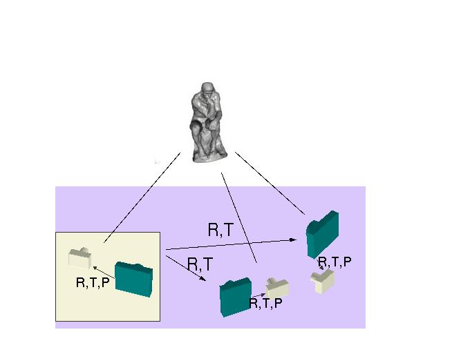
Once we have registered a set of images with one or more scanner positions, we have to combine all the textures together to produce a final textured model. There are two issues to solve at this stage: first, we have registered our images with respect to different scanner positions, but our final mesh is only aligned to one of those views; second, we have to decide, for each vertex on the mesh, which image to use if more than one is available.
The first problem is easy to solve, since we already know how all scans relate to each other. One of the scans is the "home" scan (SH), and the mesh is in the coordinate system of this scan. Suppose we have an image I which was registered with respect to another scan, S2. Since we know how to transform our points from SH to S2 (from our registration phase), then we just apply the corresponding rotation and translation to each vertex on the mesh to place them on the S2 coordinate system and then we use the computed camera registration to map the vertices from S2 to the image I.
We implement this technique through a configuration file which defines all scanner positions and a set of images registered to these scans. Such a file is shown below.
v -2.489177 0.100795 1.243494 0.041726 0.220322 -0.022632 0.974272
v 4.999800 -0.300671 -1.380753 0.016147 -0.548838 0.058731 0.833707
v 1.855267 -1.049683 -8.793119 -0.006444 -0.978156 0.076421 0.193206
v -4.782787 -0.643822 -5.957293 0.014502 0.846395 -0.072242 0.527433
v 1.730763 0.023444 0.984289 0.022677 -0.205478 0.028143 0.977994
v 0.000000 0.000000 0.000000 0.000000 0.000000 0.000000 1.000000
v 3.810982 -0.720078 -5.506021 -0.015705 -0.852357 0.118027 0.509226
t LePenseur002_l.jpg 0 mesh1_img002_ptx4.trf
t LePenseur005.jpg 1 mesh2_img005_ptx5.trf
t LePenseur012.jpg 2 mesh3_img012_ptx6.trf
t LePenseur003.jpg 3 mesh4_img003_ptx7.trf
t LePenseur006_ls.jpg 4 mesh5_img006ls_ptx9.trf
t LePenseur007_l.jpg 5 mesh6_img007_ptx1.trf
t LePenseur016.jpg 6 mesh7_img016_ptx8.trf
A line that starts with a v defines a new viewpoint by specifying a translation vector and a rotation quaternion. The above file has 6 viewpoints, the fifth being the home view. Textures are defined in lines starting with a t, in the following way:
t <img-file-name> <viewpoint-index> <transform-matrix-file>
So
t LePenseur002_l.jpg 0 mesh1_img002_ptx4.t
means that img LePenseur002_l.jpg was registered with respect to viewpoint 0 and the matrix that defines the projection of world coordinates into image coordinates is stored in the file mesh1_img002_ptx4.trf.
We now have a way to compute the image coordinates of every vertex in the mesh for every image. We then have to decide which image to use to texture each triangle. The image is selected using the following criteria:
1. Visibility criteria: Is the mesh vertex visible from the camera that took the image? If it is, then the corresponding image is a candidate image for that vertex.
2. For each candidate image, we can compute the angle between the vertex normal and the viewing direction. We then choose the one image whose angle is the smallest (or equivalently, the view direction whose dot product with the vertex normal is the greatest).Still, there is one more problem to solve. Some triangles have their vertices mapping to different images. The texture mapping procedure requires all vertices of a triangle to belong to a single image. One approach to solve this problem is to create a new texture by blending the image regions that map to these kind of triangles. We did not choose this approach due to its complexity; instead, we decided to use a "maximum consensus" approach. If two vertices in a triangle map to one image and the third one maps to another, then we use the first image as the texture source. If all vertices map to different images, we arbitrarly choose the first image.
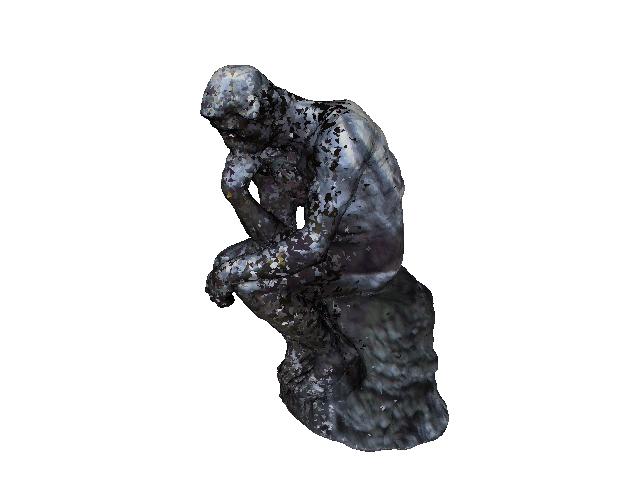
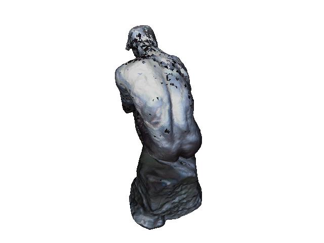
The results of our multiview texture mapping procedure are shown below.
First result-set
Configuration file:
v -2.489177 0.100795 1.243494 0.041726 0.220322 -0.022632 0.974272
v 4.999800 -0.300671 -1.380753 0.016147 -0.548838 0.058731 0.833707
v 1.855267 -1.049683 -8.793119 -0.006444 -0.978156 0.076421 0.193206
v -4.782787 -0.643822 -5.957293 0.014502 0.846395 -0.072242 0.527433
v 1.730763 0.023444 0.984289 0.022677 -0.205478 0.028143 0.977994
v 0.000000 0.000000 0.000000 0.000000 0.000000 0.000000 1.000000
v 3.810982 -0.720078 -5.506021 -0.015705 -0.852357 0.118027 0.509226
t LePenseur002_l.jpg 0 mesh1_img002_ptx4.trf
t LePenseur005.jpg 1 mesh2_img005_ptx5.trf
t LePenseur012.jpg 2 mesh3_img012_ptx6.trf
t LePenseur003.jpg 3 mesh4_img003_ptx7.trf
t LePenseur006_ls.jpg 4 mesh5_img006ls_ptx9.trf
t LePenseur007_l.jpg 5 mesh6_img007_ptx1.trf
t LePenseur016.jpg 6 mesh7_img016_ptx8.trf
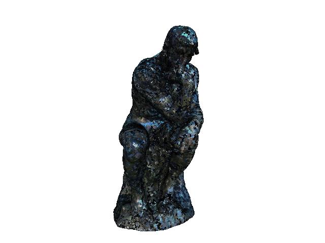
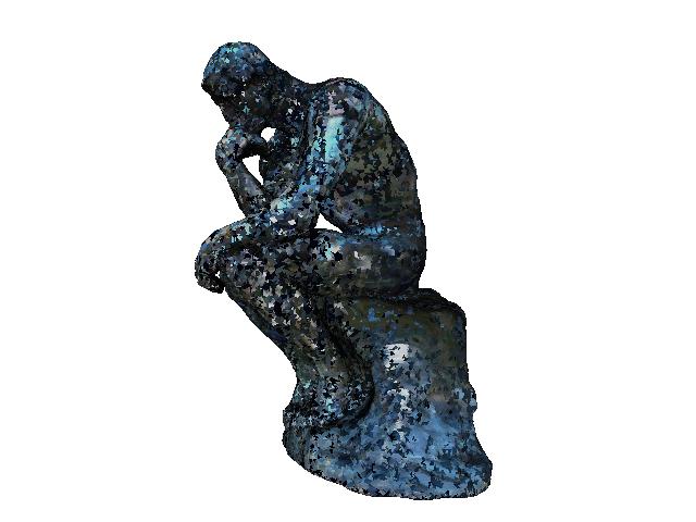
Snapshots:
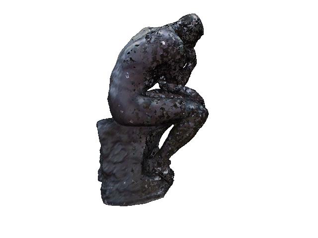
Second result-set
Configuration file:
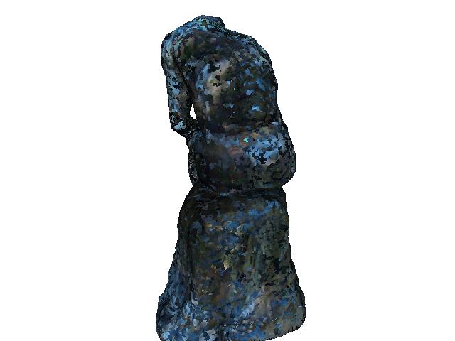
v -2.489177 0.100795 1.243494 0.041726 0.220322 -0.022632 0.974272Snapshots:
v 4.999800 -0.300671 -1.380753 0.016147 -0.548838 0.058731 0.833707
v 1.855267 -1.049683 -8.793119 -0.006444 -0.978156 0.076421 0.193206
v -4.782787 -0.643822 -5.957293 0.014502 0.846395 -0.072242 0.527433
v 1.730763 0.023444 0.984289 0.022677 -0.205478 0.028143 0.977994
v 0.000000 0.000000 0.000000 0.000000 0.000000 0.000000 1.000000
v 3.810982 -0.720078 -5.506021 -0.015705 -0.852357 0.118027 0.509226
t dscf0040.jpg 0 mesh1_img040_ptx4.trf
t dscf0039.jpg 1 mesh2_img039_ptx5.trf
t dscf0042.jpg 2 mesh3_img042_ptx6.trf
t dscf0041.jpg 3 mesh4_img041_ptx7.trf
t dscf0038.jpg 4 38-5Final.trf
Analysis of results
Our final texture mapping results do not look very good. At a glance, one can notice that images are not spanning a contiguos area of the mesh, which is what we had been looking forward to. Instead, each images is texturing a spot of triangles. This is due to the way our normals for each vertex are being computed. There are thousands of triangles on the mesh, some of them very little, and their orientations are not really smooth. This is giving our texture the "spotted" appearance. To solve this problem, we should compute a normal for each vertex as the average normal of all the triangles the vertex is a member of.
In addition, it can easily be noticed that the illumination conditions for each image are different. This makes the textures look different at the boundaries between two images (which in our case are a lot). This effect could be reduced if in a pre-processing stage we would eliminate the specular highlights and shadows and normalize the final color. A different approach could also be taken, by trying to estimate the reflectance properties from the images making some assumption about the reflectance model (e.g. Torrence-Sparrow or Oren-Nayar, it is definetively not Lambertian) and then rendering the statue using the predicted model.