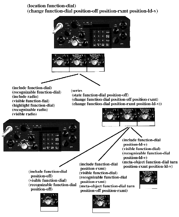
Figure 5-1. Illustrator Hierarchy.
Sometimes, a single illustration does not effectively accomplish a set of communicative goals. A series is an ordered set of illustrations that typically depict a temporal sequence of events, the steps in a procedure, or causal relations. Illustrations designed by human illustrators often are composite illustrations, to show, for instance, an ordered sequence of steps to accomplish a task. For example, the series of illustrations depicts the task, while each individual illustration depicts just one step. Composite illustrations are also used to show the same object in different states when one simple illustration is not effective. In Chapter 3 we showed how two states of the same object could be depicted in one illustration. In the example shown in Figure 3-1, one illustration depicted both the previous and next state of the knob. It would be increasingly difficult, however, to effectively depict three or more states of the knob in just one illustration. Instead, we can generate a series with individual illustrations showing the dial in each setting.
An inset is a nested illustration. Insets are used typically to show the same object appearing in the background illustration from another angle, or with greater or lesser detail. An inset illustration can be used to show context for objects in the background illustration. Thus, an inset may show the map indicating the location of the house that figures in the background illustration. An illustration may contain more than one inset. For example, the background illustration may show a house with insets that show each room.
We define a composite illustration to be a set of illustrations, which in concert, satisfy communicative intent. Our system selects to generate a composite illustration when it detects that communicative intent cannot be achieved in just one illustration. Our system currently generates series and insets.
The success of a style or design is determined during the illustration process. When one illustration cannot achieve all the goals associated with the specified communicative intent, a composite illustration can be generated and different goals are handled by each component of the illustration. Each object representation includes information to determine whether or not the object is legible in a given illustration. During the design process the illustrator determines that different objects must be recognizable and/or visible. In some cases, no one view specification can satisfy these constraints, thus no single illustration can satisfy these goals. A composite illustration can satisfy all these constraints because each individual illustration is designed to satisfy a subset of goals. Suppose the illustrator determines that certain objects must be shown in their entirety, while others must be shown at a certain resolution. No one view specification can satisfy these constraints. A composite illustration can be used to show the scene with varying degrees of detail.
In this chapter we will describe how our architecture supports composite illustrations through the use of an illustrator hierarchy. We will describe how composite illustrations are generated and the meta-rules that are used for inheritance, partitioning of goals, and the consistent use of visual cues.
Once it is determined that a composite illustration is necessary, an illustrator hierarchy is created. The root illustrator is called the master illustrator, and all other illustrators are subordinates. The master illustrator coordinates the work of the subordinate illustrators, making the final decisions for sizing and positioning. Each illustrator is assigned a partial set of goals to achieve by its parent. Thus, the system supports more than one illustrator, drafter, and illustration. Like its parent, children illustrators have an assigned a set of goals and a separate drafter and illustration. When each illustrator completes its assigned set of goals, its illustration is positioned and sized by the parent illustrator.

Figure 5-1. Illustrator Hierarchy.
Figure 5-1 shows the hierarchy of the composite illustration shown at the root of the hierarchy. This composite illustration has been designed to show the location of the function dial with highest priority and the change in state of the same dial in three different states. The master illustrator is responsible for the entirety of the communicative intent. Its first child illustrator is responsible for the location goal while its second child is responsible for the change goal. The second child has three children of its own, each assigned to show the dial in one state. The style methods are used consistently in all the illustrations, the dial is highlighted in the same way, and the view specifications for each illustration of the dial are identical.
Meta-rules embody the criteria used to determine when a composite illustration should be generated. Figure 5-2 shows the meta-rules used to determine when to generate a composite illustration.
The first meta-rule specifies that if the input communicative
intent is divided into substeps then a composite illustration
is generated. The master illustrator is assigned
the entire communicative intent while each substep is assigned to a child illustrator. For example, a COMET logical form describes steps and substeps. Each one of these substeps is assigned as a separate communicative intent to a subordinate illustrator. This mechanism is useful to coordinate the various media generators in a multimedia system. The decomposition of a task into substeps is used to coordinate text and graphics in COMET [Feiner and McKeown 91]. The group of sentences generated to explain a particular step correspond to the group of illustrations showing the various substeps. This enables the media coordinator to have greater control over the output of each generator. Of course, each substep could be assigned to each media generator directly. However, the higher-level representation enables each media generator to treat the generation task slightly differently, treating each subgoal as part of a greater whole. Just as a text generator employs specialized rules to generate a set of consecutive sentences, the illustration system employs specialized rules to generate the components of composite illustration.
The second meta-rule controls the illustrator’s backtracking. It specifies that an composite illustration is generated when a new communicative goal cannot be achieved in the current illustration. This rule is applied only when the current state of the illustration satisfies at least one other communicative goal. This rule is designed to reduce redundant computation. A new illustrator is created to handle the current state of the illustration and set of goals associated with it that are successfully achieved. This illustrator inherits all the work accomplished by the current illustrator. An inset illustrator is created and assigned the goal that caused the system to fail. It inherits the current state of the illustration, but with none of the constraints. Thus, the current illustrator becomes a parent with two children. The first child is assigned the set of achieved goals and the second child is assigned the failed goal. All subsequent communicative goals are passed from the parent to the first child. If the first child cannot achieve a new goal, it is assigned to the sibling inset illustrator(s). If none of the children can achieve the goal, a new child inset is created. In the current implementation, an inset illustrator cannot have a inset child.
1. if the input communicative intent is divided into substeps, then generate a series composite illustration in which each individual illustrator is assigned a substep
2. if an illustration satisfies one or more communicative goals and none of the methods for a communicative goal g can be achieved in this illustration, then generate an inset composite illustration and assign it communicative goal g.
3. if an illustration satisfies no goals and all design methods have been tried, select a design method and generate an inset composite illustration for the first style strategy goal that fails
4. complete illustrations in the order they were assigned (as specified by the communicative intent)
Although it should be possible to find one design method to accomplish a communicative goal in one illustration, the third meta-rule is added to handle situations in which all solutions fail. For example, it may be impossible to show an object in its entirety and for it to be legible in the same illustration, although many design rules assert both subgoals for the same object. In theory, this case arises because the recognizability and/or visibility constraints associated with a particular object are overly constrained. We will show in the next chapter how this mechanism is used to handle goal violations during interactive sessions, when other factors introduce more constraints. This rule specifies that if no solution can be found with existing design methods, then the preferred design method is selected and applied. When one of its style methods fails, a composite illustration is used and the style method is assigned to another illustrator’s drafter.
In Chapter 3 we showed that the illustrator and drafter, unless specified otherwise, address goals in the order that they were input. The fourth meta-rule specifies that each goal be handled in the order it was input.
Each illustration in a composite illustration is part of a whole. If several illustrations of the same scene include different sets of objects, then the overall effect could be confusing. Similarly, if different visual cues are used to convey the same concept, then the effectiveness of the communication may be lessened and the false implication that the concepts depicted by both visual cues are different may be introduced. The meta-rules in Figure 5-3 are designed to maintain consistency among the components of a composite illustration.
5. a child illustrator inherits the current state of its parent (rule ordering and illustration)
6. a child illustrator reorders methods so that methods that are currently being used are preferred
7. if no design method succeeds, then the preferred method will always be used (by rule 3, an inset will be generated for the first style strategy that fails)
8. when all illustrations are completed adjust the view specifications to be consistent (if possible)
The fifth meta-rule specifies that a child illustrator inherits its parent’s illustration. This mechanism is designed to avoid unnecessary computing. The child illustrator incrementally adjusts the illustration to satisfy the goals it is assigned. It begins with a copy of the illustration, including the illustration-objects and inherits the rule orderings of its parent.
The sixth meta-rule specifies that visual cues should be used consistently across the illustrations of a composite illustration. In Chapter 3 we showed how both the illustrator and drafter reorder all methods before beginning to try to accomplish a particular goal. This rule is applied to change the ordering of methods so that those already in use are tried first. For example, if the method for generating red arrows to show “turning” is applied in one illustration, then that method becomes the preferred method for showing “turning.” However, if goals are violated, alternative methods are tried, so the preference is overridden. This unfortunately has the side effect of causing the system to possibly select a less optimal solution. However, alternative methods will be chosen if the current method is not evaluated as successful (meeting the minimum threshold).
The seventh meta-rule is used when the illustrator cannot achieve a communicative goal and has not achieved any other communicative goals. This rule is used in conjunction with the third meta-rule. The illustrator fixes the preferred method for that goal. The style strategy goals will then be distributed over the components of the composite illustration when the first style strategy subgoals fails.
The eighth meta-rule specifies that jarring and unnecessary differences in the view specification should be eliminated between the components of a composite illustration. For example, the view specification chosen for two illustrations may differ unnecessarily. Once every illustrator has satisfied its set of assigned goals, this rule is applied to select a common view specification. The resultant view specification is designed to comply with the goals associated with each illustration. Suppose the system is assigned the task to show three steps of turning dials on the radio. Figure 5-4 shows the composite illustration generated without applying this rule, while Figure 5-5 shows the same composite illustration after this rule is applied. This is accomplished by averaging the values that define the view specification. Currently we compute the midpoints of the lookat points, average the recognizability vectors and adjust the camera’s location so that important objects are not clipped.
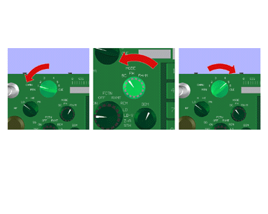
Figure 5-4. Composite Illustration. No rules for consistent views.
A series is a composite illustration that represents a sequence of steps that are ordered temporally and grouped together. Figure 5-6 shows the methods for sizing and positioning series illustrations. The preferred method specifies that the illustrations be equally sized, centrally aligned, and positioned on the horizontal axis from left to right (low to high along the horizontal axis in Figure 5-6).
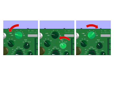
Figure 5-5. Composite Illustration. Rule for consistent view applied.
(methods series-sizing
equally-sized
sized-by-suggested-ranges)
(methods series-alignment
align-by-center
align-by-bottom
align-by-top)
(methods series-position
horizontal-axis
vertical-axis
diagonal-axis)
(methods series-order
low-to-high
high-to-low)
An inset is a smaller illustration positioned inside a larger illustration. Figure 5-7 shows the methods for sizing and positioning inset illustrations. The preferred method specifies that the inset be placed so that common objects are aligned and that it be sized using the ranges returned by the illustrator. The placement of the inset illustration must not violate the visibility goals associated with the objects in the illustration it covers.
(methods inset-position
aligned-to-common-object
bottom-right
bottom-left
top-left
top-right
free)
(methods inset-sizing
sized-by-suggested-ranges
one-fourth-of-parent
one-fifth-of-parent
one-sixth-parent)
Figure 5-8 shows the communicative intent specifying the illustration shown in Figure 5-9. The illustration is designed to show how the four latches that attach the battery pack to the radio are snapped into place. In brief, the illustrator successfully achieves the change goals for the first three latches but fails at the change goal for latch4. The illustrator cannot find a view specification in which all four latches are both visible and recognizable. This causes the illustrator to generate a composite illustration and assign to an inset illustrator the change goal for latch4. We will now describe how this illustration is generated.
(change latch1 snap unsnapped snapped
user battery-pack radio
highest)
(change latch2 snap unsnapped snapped
user battery-pack radio
highest)
(change latch3 snap unsnapped snapped
user battery-pack radio
highest)
(change latch4 snap unsnapped snapped
user battery-pack radio
highest)
(location latch1 radio medium)
(location latch2 radio medium)
(location latch3 radio medium)
(location latch4 radio medium)
In this example only general rules and methods are used. The only specialized knowledge that is used concerns the object’s recognizability and context object.
The illustrator is assigned the communicative intent and the first communicative goal, to show the change in latch1, is assigned to the illustrator. The illustrator selects the design method shown in Figure 5-10 to achieve this goal.
The first style strategy goal is:
(include latch1 snapped highest)
An illustration-object is created to directly correspond to the description in the knowledge-base. The latch1 has a specialized shape “latch” that consists of two parts: body and catch. The material value is specified as “metallic white paint.” The location and orientation information is retrieved for the instance of the latch1 in the state “snapped” and assigned to the illustration-object. An object-relation is created which points to the new illustration-object and physical object in the knowledge-base.
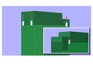
Figure 5-9. Composite illustration showing how latches are snapped.
(method-for-change-with-highest-priority
;; ASSIGNED TO ILLUSTRATOR
(change ?object ?action ?from ?to ?agent ?object-list highest)
=>
;; ASSIGN TO DRAFTER
(include ?object ?to highest) ;;1
(context ?object highest) ;;2
(visible ?object ?to high) ;;3
(recognizable ?object ?to high) ;;4
(ghost ?object ?from high) ;;5
(meta-object: arrow ?object ?from ?to ?agent highest) ;;6
)
The second style strategy goal is:
(context latch1 highest)
The radio is specified as the appropriate context object for each latch. An illustration-object is generated for the object radio that includes all the descendant object of the radio. An object-relation is created which points to the new illustration-object and the radio’s physical object in the knowledge-base.
The third style strategy is:
(visible latch1 snapped high)
This visible goal is not handled at this time since no view specification and window mapping values are set. If this goal were the last goal of the method, and still no values defined a view specification, then a view specification would be selected.
The fourth style strategy goal is:
(recognizable latch1 snapped high)
The representation for latch1 includes recognizability knowledge. It specifies that at least three sides should be shown. This is represented with four vectors that represent the ideal angles by which the object should be viewed. The view specification is specified by using the first angle recommendation and the center point of the object is used to specify the reference point. This triggers the visibility goal; window parameters are set to a larger area than latch1’s bounding box.
The fifth style strategy goal is:
(ghost latch1 unsnapped high)
The ghost goal is to generate a ghost object to represent the object in the “from” state. An illustration-object is generated for latch1.ghost. However, the orientation and position values for the state “unsnapped” are used and the material value of this illustration-object is set to be partially transparent. All meta-objects have visibility goals automatically associated with them.
The sixth style strategy is:
(meta-object arrow latch1 unsnapped snapped user highest)
The goal is to generate an arrow-shaped meta-object. Using the “from” and “to” state position values, a straight arrow style is selected. This arrow is sized using the dimension of latch1 and positioned using the bounding box of the ghosted-object. The endpoints of the arrow are positioned at the centers of the latch in both states, the arrow is pointed towards the destination state. The object inherits the scaling from the latch. If we were to change the scale of the latch and restart the system, the arrow’s width would reflect this change. Again, a visibility goal is associated with the meta-object. The view specification is changed so that the ghost object and arrow will be visible in the illustration.
At this point, all style strategy goals are evaluated as successful. The evaluator for the change goal is activated and returns success. The current state of the illustration is shown in Figure 5-11. The methods are reordered, so that methods currently in use are tried first.
The illustrator proceeds to the next communicative goal:
(change latch2 snap unsnapped snapped user battery-pack radio highest)
The methods are reordered, so that methods currently in use are tried first and the illustrator selects the same method to show change.
The first style strategy is:
(include latch2 snapped highest)
The include goal is satisfied in a different way. The relation for the radio specifies that the illustration-object for the radio includes latch2. It is removed from the radio illustration-object and a new illustration-object is created for latch2.
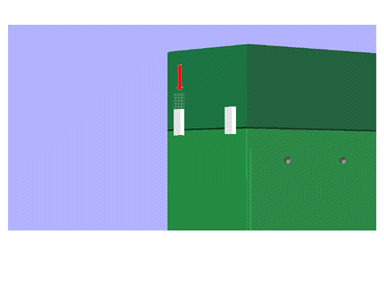
Figure 5-11. Illustration after change goal for latch1 is successful.
The second style strategy is:
(context latch2 highest)
Context is evaluated as successful so nothing occurs.
The third style strategy is:
(visible latch2 snapped high)
The visibility goal for latch2 is satisfied by changing the view specification. The reference point is set to the midpoint between latch1 and latch2. The other goals are satisfied in the same way described for latch1. The method for showing change of latch2 is successful.
The fourth style strategy is:
(recognizable latch2 state snapped high)
The recognizability constraints associated with latch2 are used to satisfy this goal. A set of recognizability constraints is maintained. The intersection of this set and the new constraint is computed. The recognizability constraints were identical for both latches so the set remains unchanged. A ghost for latch2 is generated along with a red arrow in the same manner as for latch1. The state of the illustration at this point is shown in Figure 5-12.
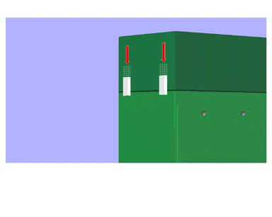
Figure 5-12. Illustration after change goals for latch1 and latch2 are successful.
The illustrator is assigned the next communicative goal:
(change latch3 snap unsnapped snapped user battery-pack radio highest)
The system proceeds in the same way as for latch2 until it reaches the visibility goal. The reference point is set to the midpoint between latch1, and latch2, and latch3. The recognizability goal is handled next. New values for the view specification are computed. First, the intersection of the two sets with the four angles for latch3 is empty. A simple procedure is then used to generate new angles that are averages of the angles in both sets. These are ordered by deviance from the original angles, so that the angle that most closely matches its parents is used. The evaluation for recognizability still returns a high rating since the deviance from the original angle is not high. The visibility goal is activated again for all the objects and evaluates high for all nine objects.
The state of the illustration after successfully completing the first three communicative goals is shown in Figure 5-13.
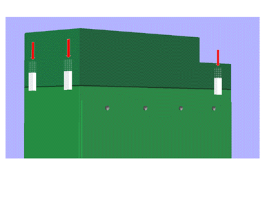
Figure 5-13. Illustration after change goals for latch1, latch2, and latch3 are successful.
The illustrator is assigned the next communicative goal:
(change latch4 snap unsnapped snapped user battery-pack radio highest)
The process continues until the visibility goal for latch4 is addressed. The only views in which all ten objects are visible are from the back of the radio as, for example, the one shown in Figure 5-14. All of these views violate the recognizability constraints associated with the latches. The system backtracks to the point shown in 5-13. The second meta-rule in Figure 5-2 is applied which specifies that a composite illustration be generated. The current illustrator becomes a master illustrator, and two new illustrators are created. One is assigned the currently solved change goals and inherits the complete solution generated. The second is assigned the change goal for the fourth latch. It too inherits the current illustration with constraints on the view specification removed. The illustrator is assigned the style preference. Both illustrators manage illustrations with the same objects. The second illustrator begins to satisfy the change goal. The include goal succeeds after latch4 is extracted from the radio object and assigned a new illustration-object. The context goal is successful. The other goals for latch4 are handled in the same way as the goals were for latch1. When the arrow and ghost objects for latch4 are created for the illustration, the first illustrator inherits them as well. This mechanism ensures that all components of a composite illustration include the same set of objects.
The master illustrator still has four location goals to satisfy. It assigns each to the first illustrator and then to the inset illustrator if there is failure. In Chapter 3 we described the location design method in detail. The first illustrator satisfies the location goals by adjusting the view specification so that landmark objects are shown. The first illustrator is not able to solve the location goal for the fourth latch. The master illustrator assigns it to the inset illustrator. The inset illustrator satisfies the location goal by adjusting the view specification so that the radio’s landmark objects are shown. The constraints associated with each illustration are augmented so that the battery pack will be recognizable. The inset illustration is shown in Figure 5-15.
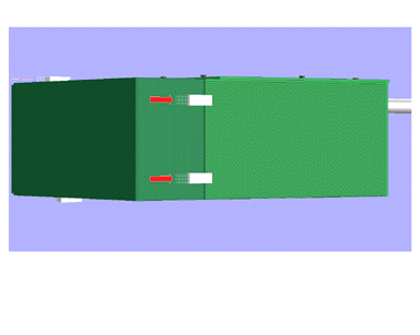
Figure 5-14. View specification that satisfies visible goals but violates recognizable goals.
Now there are two illustrations, with identical illustration-objects and different view specifications. The first illustration is mapped onto the prescribed screen area. The extent of the window is based on the bounding box of the battery pack (the largest object that must be visible). The inset is positioned and no goals are evaluated as unsuccessful. The final illustration is shown in Figure 5-9.
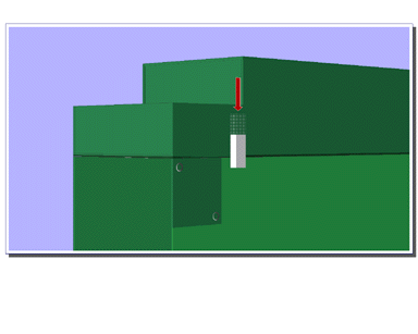
Figure 5-15. Inset illustration to solve the change goal for latch4.
We have shown how our system generates two types of composite illustrations when a single illustration cannot achieve communicative intent. Series are generated to depict a sequence of steps or causal relationship. Insets are generated to achieve communicative goals that cannot be achieved in the main illustration. Thus, composite illustrations are a mechanism for handling overly-constrained communicative intent.
For example, the visibility or recognizability goals assigned for each object may conflict and no single illustration can be designed to achieve all of them. For instance, the view specification is constrained to show one subpart from a particular angle and another subpart in its entirety. When the view specification is changed to satisfy the first constraint, the second object is clipped, thus violating the second constraint. When a solution cannot be found, a composite illustration is designed so that both constraints are satisfied in one or more components of the composite illustration.
We have shown how each illustration in a composite illustration is generated using meta-rules to favor solutions that use visual cues consistently and that have a consistent view specification, when possible. We have also shown that our architecture is able to handle composite illustrations with little modification. In Chapter 3 we described how our system generates a sequence of illustrations, one at a time, while maintaining information such as the current state of the objects in the world. We apply the same mechanisms to generate the set of illustrations that make up a composite illustration. Our system is augmented in three ways. First, the system is modified to support illustrator hierarchies. Second, meta-rules are introduced to determine when to generate a composite illustration, control inheritance, and ensure a consistent use of methods. Third, a new type of illustrator, a master illustrator, is introduced, to apply the composite-illustration specific rules to position and size the illustrations generated by subordinate illustrators.