Shape from Brightness |
|||||||||||||||||||||
 |
|||||||||||||||||||||
|
We are interested in developing sensing methods and recovery algorithms for computing the reflectance and geometry of objects from one or more images. Unlike stereo or structure from motion, the images are typically captured from a single viewpoint and the object properties are computed explicitly from scene radiance values.
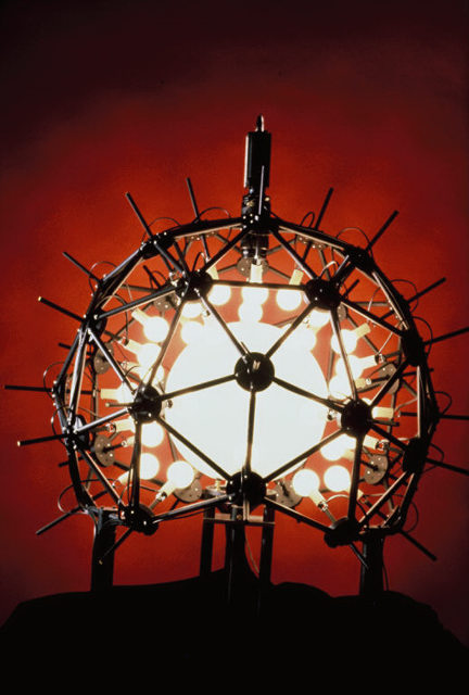
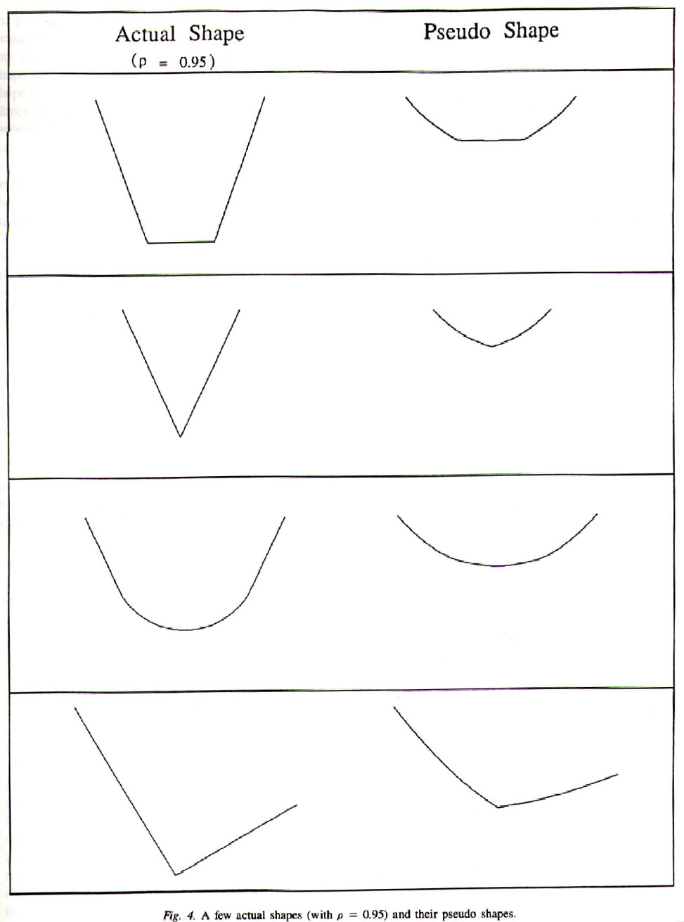
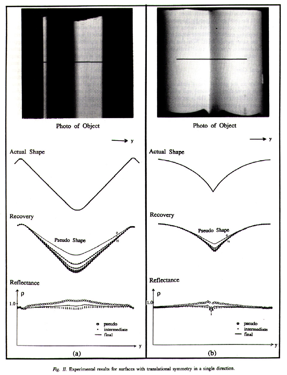
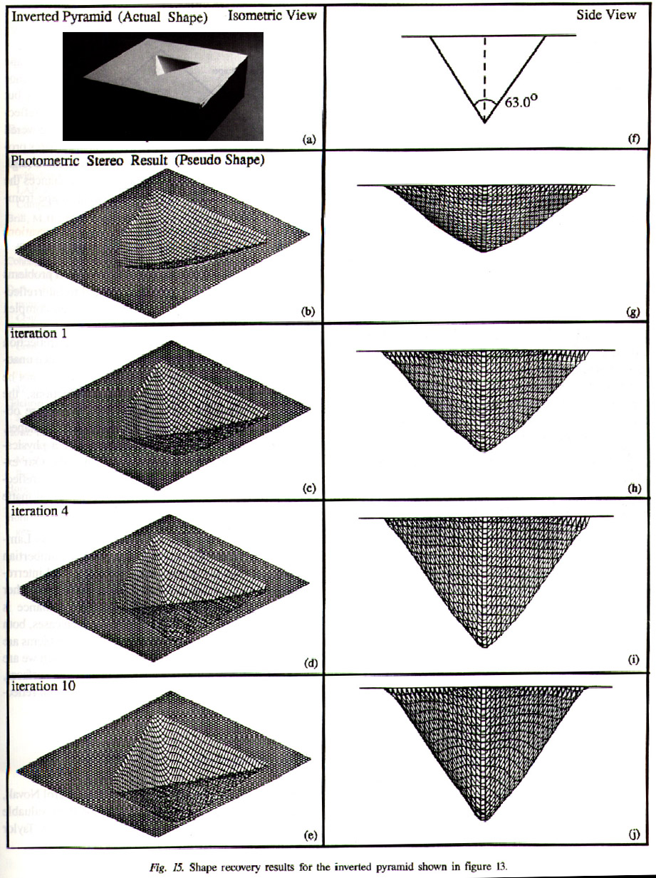
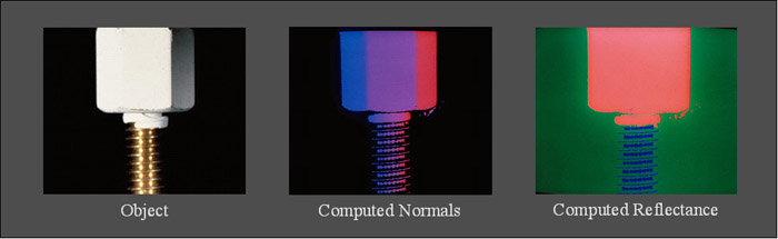
The structured highlight method recovers the surface normals of a highly specular object. It uses a dense array of light sources and is able to scan the set of sources efficiently by using binary coding. This system was used by Westinghouse Corporation for inspecting solder joints on surface-mount circuit boards. The photometric sampling method is an extention of photometric stereo. It uses a set of images captured under extended light sources placed in different directions and a physically-based surface reflectance model to recover the shapes and reflectances of complex objects (see the above image). Unlike traditional photometric stereo, this method can handle an entire spectrum of objects that goes from pure specular to perfectly diffuse. This method was developed based on the observation that the brightness of a scene point can be expressed as a convolution of the reflectance and the lighting of the point. Finally, we have studied the recovery of diffuse objects in the presence of interreflections. In particular, we have analyzed the interreflections produced by concave Lambertian objects and shown that a method like photometric stereo recovers incorrect (pseudo) shape and albedo function which are invariant to the light source directions used. An algorithm is then used to recover the actual shape and albedo function of the object from the pseudo ones. Most of this project was done at the VASC Laboratory in the Robotics Institute at Carnegie Mellon University. |
|||||||||||||||||||||
Publicationsprint_paperentry_byid: more than 2 or no entry matches. |
|||||||||||||||||||||
Pictures
|
|||||||||||||||||||||
Related ProjectsSpecularities in Stereo and Motion |